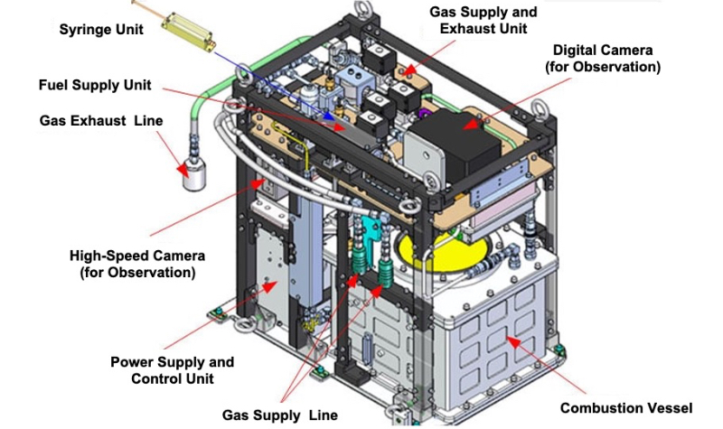
The Group Combustion Experiment Module (GCEM) is Japan's first system for combustion experiments in orbit, designed for examining the combustion mechanism of fuel droplets cloud (group of fine fuel droplets simulating sprayed liquid fuel).
Combustion experiments on Earth will cause a heavy natural convection due to the temperature difference between the high-temperature flames and the surrounding atmosphere. In a microgravity environment on the other hand, heat causes no natural convection and researchers can observe precisely combustion, focusing on the essential phenomenon.
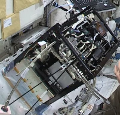
Configuration of GCEM
The GCEM consists of a combustion vessel, a fuel supply unit, a observation unit, a power and communications control unit, a gas suppy and exhaust unit, and a gas cylinder.
Combustion Vessel
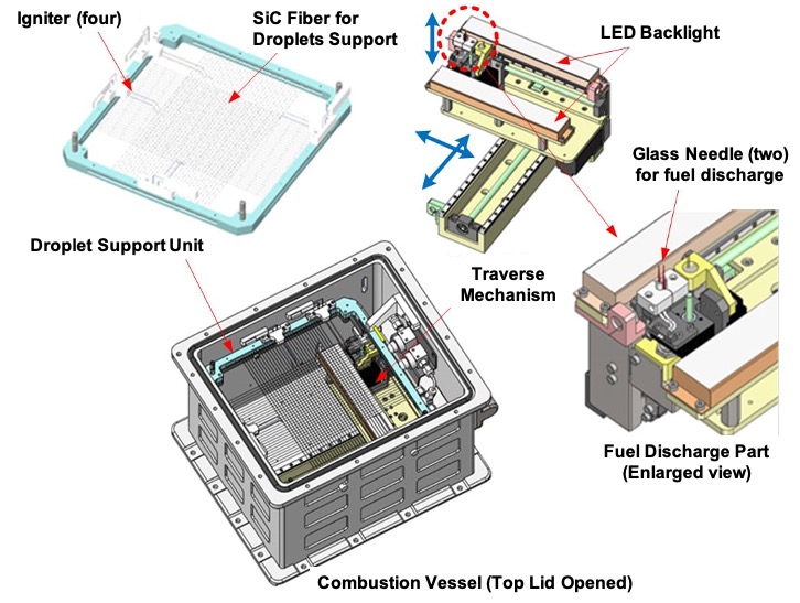
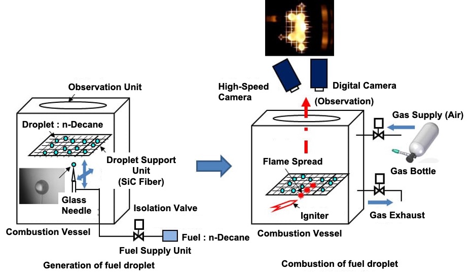
Combustion experiments on fuel droplets cloud are carried out in the combustion vessel which houses a droplets holding system for positioning fuel droplets in desired positions, a traverse mechanism for generating fuel droplets in the desired locations of the droplet holding system, and other mechanisms.
The droplet holding system consists of two arrays of 30 straight fiber lines (fine threads) (14 μm in diameter, with 4 mm spacing) which intersect at right angles to one another in the frame and a single straight fiber thread (78 μm in diameter). Fuel droplets can be placed at desired intersection points and desired locations on the fiber lines.
The combustion vessel has mechanisms (electrically heated wires) for igniting fuel droplets positioned on one end. Fuel is discharged through the 50-μm glass pipe needles (syringe needle-like elements) on the end.
These glass pipe needles are placed on the traverse mechanism which is movable in triaxial directions in the combustion vessel. From these needles, fuel droplets having desired diameters (0.7 to 2.0 mm) can be generated at desired locations on the droplet holding system.
Fuel Supply Unit
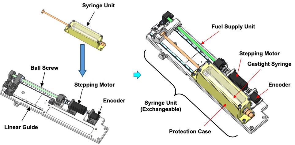
The liquid fuel to be used in experiments is stored in the syringe unit. The rear part (plunger) of the syringe unit is accurately pushed with a motor-driven mechanism to travel a desired distance. This action allows a desired amount of fuel to be delivered from the ends of the glass pipe needles in the combustion vessel which are connected by means of tubes with the syringe.
Observation Unit
The observation unit consists of a digital camera and a high-speed camera. The former is used to monitor the behavior of flames (video image) and measure the diameters of generated fuel droplets (still image).
The latter, dedicated to monitoring of the events on the straight fiber lines. Still pictures of flames and droplets can be taken at a rate of 1000 frames per second.
Power and Communications Control Unit
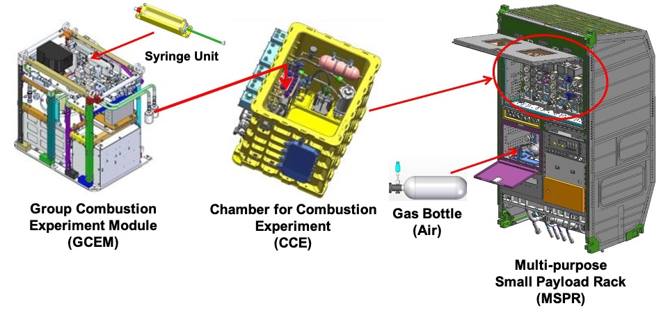
The Power and Communications Control Unit receives electrical power provided by the Multi-purpose Small Payload Rack (MSPR), controls the GCEM components and communicates with the ground station.
Gas Supply and Exhaust Unit
The Gas Supply and Exhaust Unit controls the air supply to the combustion vessel and exhaust gases after combustion. This system leads the nitrogen gas from the JEM Kibo and the air from the gas cylinder to the combustion vessel. After combustion, the gas in the combustion vessel is filtered to remove impurities and discharged through Kibo's waste gas line into space.
Gas Cylinder
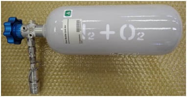
The gas cylinder contains a strictly formulated air of 100 atm (21% oxygen and 79% nitrogen). The air to be used in the combustion vessel is retrieved from this cylinder. A great amount of air is needed for conducting many experiments. Whenever the amount of air left in the cylinder becomes small, the crew replaces it with a fresh cylinder.
Sketch of Experiment
To carry out an experiment, GCEM is placed in the Chamber for Combustion Experiment (CCE) and the GCEM/CCE assembly is mounted on MSPR.
Unless specified otherwise, rights to all images belong to ©JAXA


