A MULTI-USER EXPERIMENT FACILITY TO INVESTIGATE FLUID PHYSICS PHENOMENA IN A MICRO-GRAVITY ENVIRONMENT
Overview
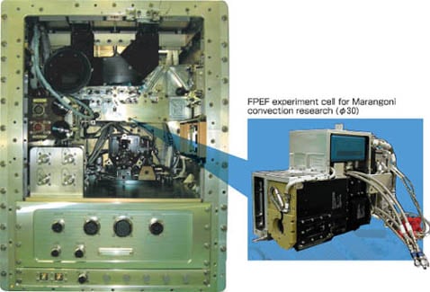
Experiment facility to investigate fluid physics phenomena in a micro-gravity environment
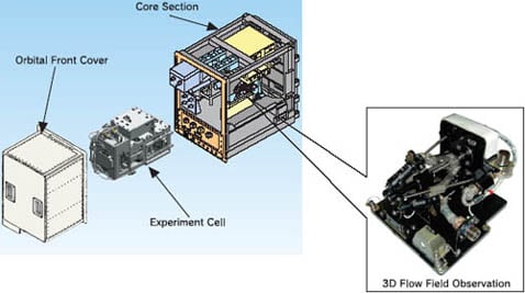
The FPEF consists of the core section and the mission section. The core section has observing equipment, the control equipment, and miscellaneous experiment support systems.
The mission section called as the "Experiment Cell", is exchangeable according to the purpose of the experiment.
The FPEF's observation capabilities include liquid bridge overview observation, three- dimensional flow field observations, surface- temperature measurement, ultrasonic velocity profile measurement, and surface-flow rate observation.
Resources for experiments
Various resources provided to users
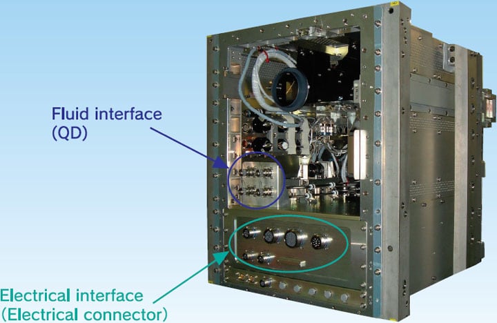
The FPEF provides users' experiment cells with electrical resources through electrical connectors and fluid resources through Quick Disconnect (QD)s. [Electrical Resources] ·Power ·Signal ·Video etc. [Fluid Resources] ·Ar gas ·Water coolant
Users can conduct a variety of fluid experiments utilizing these resources.
Experiment cell
Development of the Experiment Cell for Marangoni convection research
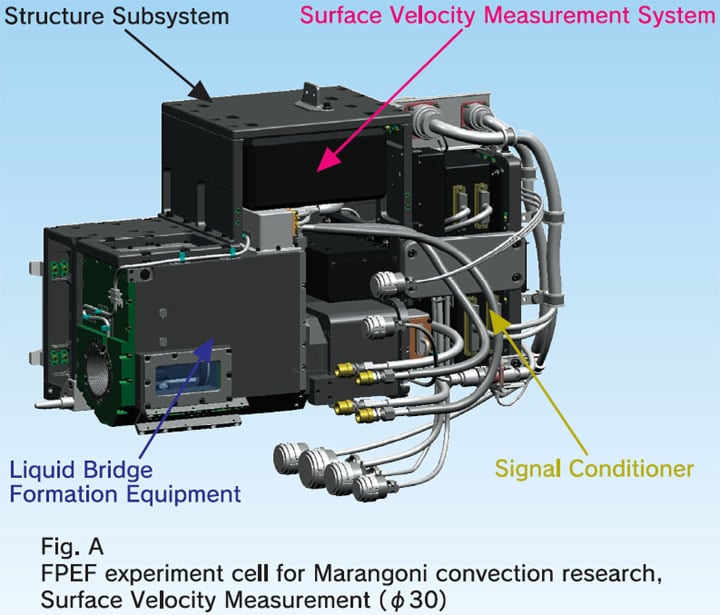
FPEF experiment cell for Marangoni convection research, Surface Velocity Measurement (φ30)
The Experiment Cell is exchangeable according to the experiment purpose.
Fig. A shows an FPEF experiment cell for Marangoni convection research, Surface Velocity Measurement (φ30) which is currently being developed.
The experiment cell consists of liquid bridge formation equipment, heating disk, cooling disk, sample cassette, surface-flow velocity measurement assembly, and structure subsystem.
It is also permitted to users to design and fabricate their own mission section determined by themselves, providing that it satisfies the core/mission section interface
Experiment operation
Flexible experiment operations and provided experiment image data
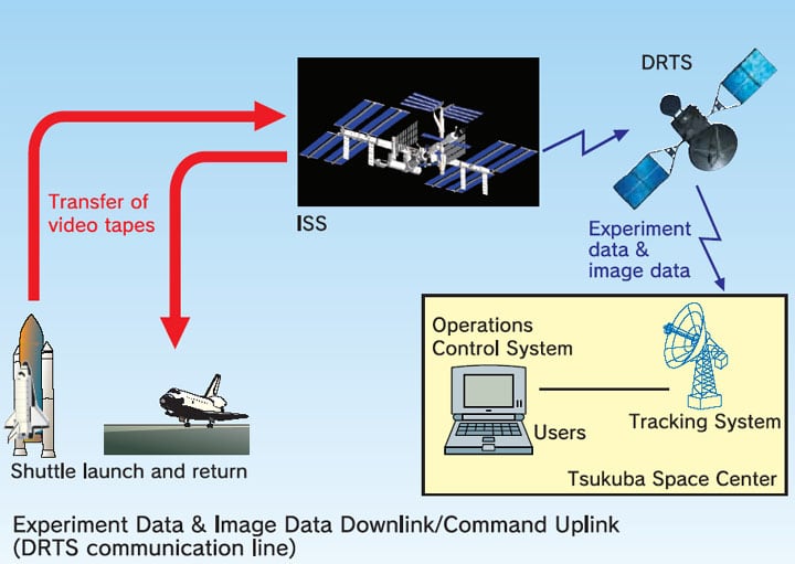
Users can conduct their experiments most appropriately by commanding experiment parameter changes from the ground.
Users can monitor both the status of experiment data measured by each sensor and the experiment image data via a satellite circuit in real time.
The experiment image data are downlinked to the ground for real-time monitor, and at the same time, recorded on the built-in digital Video Tape Recorder (VTR) for later analysis.
Specifications
| Item | Specifications | |
| Liquid Bridge Formation | Sample | Silicone oil (5 [cSt] / 10 [cSt]) |
| Tracer | Metal-coated polymer particle(φ180 [µm]) | |
| Diameter | 30[mm] / 50[mm] (diameter) | |
| Length | Max. 60[mm] | |
| Adjustable range(fluid volume) | ±9.6 [cc] | |
| Temperature Monitor | Heating Disk Temp. | 10 to 100 [deg.C] |
| Cooling Disk Temp. | Room Temp. to 0 [deg.C] | |
| Observation Window Temp. | Room Temp. to 60 deg.C] | |
| Ambient Temp. | Room Temp. to 100 [deg.C] | |
| Liquid Bridge Internal Temp. | 0 to 100 [deg.C] | |
| Temperature Control | Heating Disk | Max. 90 [deg.C] |
| Cooling Disk | Min. 5 [deg.C] | |
| Observation Window | Max. 50 [deg.C] | |
| 3D Flow Field Observation | Monochrome 1/2" CCD Camera (x 3) |
Effective pixels 768(H)x494(V) |
| Strobe Light | Flash rate 60 [Hz] | |
| Liquid Bridge Overview Observation | Color 1/3" 3CCD camera |
Effective pixels 768(H)x494(V) |
| Light *use 3D Flow Field Observation Strobe Light concomitantly | ||
| Surface Temperature Measurement | Infrared | Spectral response 8 to 14 [µm] |
| Imager | Measurement range 0 to 100 [deg.C] | |
| Surface Flow Velocity Measurement | Photochromic dye actuation with nitrogen gas laser | Two points irradiation Flash rate 4.57x10⁻⁴ to 10 [Hz] (±1%) Flash time 1 to 4097 times |
| Light *use 3D Flow Field Observation Strobe Light concomitantly | ||
| Ultrasonic Velocity Profile Monitor | UVP | Measurement point 150 (Max.) Space resolution 0.47 [mm] / 5 [Hz] (Min.) Measurement range 0.47 to 61 [mm/sec] |
| User Interfaces | Power source | 12 ± 2 [V], 4 [A] (Max.), 1 ch 24 ± 2 [V], 3.5 [A] (Max.), 1 ch ±15± 0.5 [V], 0.8 [A] (Max.) / ch, 3 ch |
| Power control | 4 to 65 [V] / 5 to 180 [W], 3 ch 1 to 30 [V] / 5 to 180 [W], 1 ch |
|
| Solenoid valve interface | 24 ± 2 [V], 1.3 [A] (Max.), 3 ch | |
| Motor drive interface | 24 [V], 3 [A], 4 ch (Model PK543-A) | |
| Analog interface | 0 to 10 [V], 8 ch | |
| Digital interface (input) | 8 ch | |
| Digital interface (output) | 8 ch | |
| Contact interface | 15 ch | |
| Pt sensor interface | 5 ch | |
| Thermocouple interface | 6 ch (K type Thermocouple) | |
| CCD camera interface | 1 ch (Model IK-TU40D) | |
| Video interface | 2 ch (NTSC) | |
| Envelope | 230(W) x 580(L) x 363(H) [mm] Note: A portion of above envelope includes space user can't use. |
|
| Argon gas supply | 88.2 [kPa] to 101.3 [kPa], 20 [NL/min] | |
| Cooling water | 8.5 [kg/h], in 16 to 23 [deg.C], out up to 43 [deg.C] | |
| Waste gas | 0.13 [Pa] to 101 [kPa] | |
| Maximum supply power (Exhaust heat) |
255 [W] (TBD) | |
Unless specified otherwise, rights to all images belong to ©JAXA